
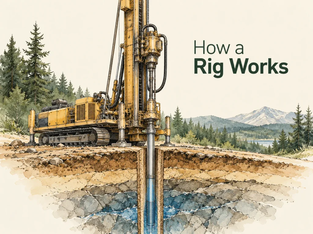
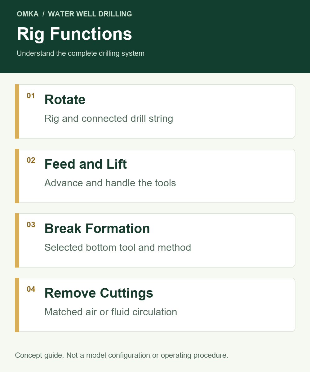
A water well drilling rig supplies the rotation, feed and lifting needed to advance and handle a drill string. The drilling method determines how the formation is broken, while the supporting air or fluid system carries cuttings away from the bottom of the hole. Understanding these separate jobs makes equipment selection easier: the rig, drilling tools and circulation equipment must work as a system.
For a buyer, the useful question is therefore broader than whether a machine has enough advertised depth. You need to understand what produces the cutting action, what moves the tools, what clears the hole and what handles the drill string. This guide explains those functions and their relationship to a water well project, without turning a general explanation into a model-specific operating procedure.
The Main Functions of a Water Well Drilling Rig
Rotation and Rock-Breaking Tools
The rotary head turns the connected drill string. That rotation reaches the tool at the bottom of the borehole through the drill rods and their connections. The bottom tool, selected for the drilling method and formation, acts on the material being drilled. Rotation is one part of the process; the tool design determines how it is used.
In a down-the-hole, or DTH, arrangement, a pneumatic hammer is positioned near the drill bit. The hammer provides percussion at the bottom of the hole, while the rig provides rotation and the feed needed for the selected tool. These separate roles are described in Epiroc’s DTH hammer instructions. It is misleading to describe every rotary water well rig as a machine that directly hammers the rock. The source of percussion and the supply system depend on the actual configuration.
Feed and Lifting
Feed moves the drilling assembly along the mast and helps apply the working action required by the method. Lifting withdraws and handles the connected tools. These functions have different roles from rotation, so a torque figure cannot replace a lifting figure when comparing machines.
Rod handling connects the theoretical drilling capacity to practical equipment use. Mast travel, rod length, clamps and handling accessories influence how the drill string can be assembled and managed. A buyer should identify the proposed rod arrangement rather than assume that any rod length in a catalogue works with every handling configuration.
Removing Cuttings
Breaking the formation creates cuttings. If those cuttings remain where the tool is working, making new material available to the cutting surfaces becomes more difficult. The circulation system provides a route for moving the cuttings away.
Air and liquid circulation are different ways of performing this task. Their requirements involve the tool, borehole and return path, not just the power of the rig. A drill that can rotate and lift tools still needs a suitable circulation arrangement for the selected method.
What Happens During the Drilling Process?
Advancing the Drill String
At a conceptual level, the bottom tool acts on the formation while the rig advances the drill string. As the borehole becomes deeper, additional rods may be incorporated according to the equipment arrangement. The connected rods transmit rotation and provide the internal flow path used by many drilling systems.
This explains why the rods are part of equipment selection rather than an accessory chosen at the end. Their length, diameter, connections and handling requirements must be considered alongside the rig. The total drilling assembly also changes as depth increases, so a short initial setup does not represent every later stage of the task.
Carrying Cuttings Away
In an air-drilling system, compressed air is delivered through the drilling assembly and used in the selected tool and circulation path. In a conventional direct fluid-circulation arrangement, liquid travels down the drill string and returns with cuttings through the space outside it. The exact arrangement must follow the method and equipment documentation.
That outside space is commonly called the annulus. Its geometry depends on the borehole and drill string, which is one reason borehole diameter matters beyond the size of the finished opening. Choosing supporting equipment requires an understanding of the full flow path, including what happens when the returning material reaches the surface.
Managing the Borehole and Handling Tools
Different formations can present different requirements for keeping a borehole suitable for continued work. Casing, a selected circulation method and other project-specific measures may form part of the well design. These are connected to equipment scope, but they are not interchangeable decisions.
The drilling stage is also only part of producing a usable water well. Completion, development and assessment of water quantity and quality involve separate project requirements. A rig’s ability to drill a hole does not prove that the site will provide the desired water supply.
How Do Air Rotary, DTH and Fluid-Circulation Methods Differ?
Air rotary describes an arrangement using rotation and air circulation with the selected bottom tool. DTH drilling adds a hammer near the bit, where compressed air serves the hammer and the circulation system. Both involve air, but that shared medium does not make the tool arrangements identical.
Fluid circulation describes the use of a liquid drilling medium in the circulation path. The pump, fluid system and tools must suit the planned method. Referring to all liquid circulation simply as “mud drilling” can hide important differences in the actual medium and equipment arrangement.
Swipe or scroll the table to compare all columns.
| Question | Air Rotary | Air DTH | Direct Fluid Circulation |
|---|---|---|---|
| What identifies the arrangement? | Rotary tool with air circulation | Bottom hammer with air supply | Liquid circulated through the drilling system |
| What must be identified? | Bit and air requirements | Hammer, bit and air requirements | Tools, pump and fluid-system requirements |
| What should the buyer avoid assuming? | Every air system uses a hammer | Any compressor suits any hammer | The pump alone determines borehole stability |
Use this comparison to identify the method before comparing equipment. “Hydraulic” normally describes a drive or control arrangement; “crawler” and “truck-mounted” describe platforms. Neither term replaces the drilling-method description. A crawler rig can have hydraulic functions and a DTH configuration without those three descriptions contradicting each other.
The formation information helps the project team assess a method, but a simple rock-versus-sand slogan is not a complete equipment decision. Mixed or incompletely known ground needs a more careful review of the proposed tools, circulation and borehole-management requirements.
What Supporting Equipment Does the Rig Need?
Air Compressor or Fluid-Circulation Equipment
An air-drilling package needs a compressor assessed against the actual tool and circulation requirements. Working pressure and airflow are separate fields. The compressor’s rating basis, the hammer documentation, distribution system and site conditions all belong in the review.
A fluid-circulation package needs the pump and associated system required by the planned method. Pump flow and pressure must relate to the actual configuration. Water or fluid supply, return handling and solids management can change the scope substantially, so purchasing a pump is not the same as defining a complete circulation system.
Drill Rods, Bits, Hammers and Connections
The drill string connects the rig to the bottom tool. Rod connections must match the relevant components, and the tool arrangement must suit the selected drilling method. Similar-looking threads or a familiar hammer size are not enough to establish compatibility.
Good procurement descriptions identify the component, model or connection specification, quantity and relevant drawings. This makes it possible to review the system before dispatch rather than discover an unresolved interface when equipment arrives at the site.
Handling Equipment and Supply Scope
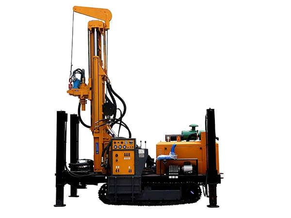
Handling arrangements may include equipment associated with rods, tools and loading, depending on the rig and package. The purchase scope should distinguish the basic machine, agreed options and customer-supplied items. A photograph is useful for understanding a machine, but it is not a binding list of included accessories.
Documentation belongs in the same discussion. The purchaser needs the correct manuals and identification information for the supplied configuration. Training and support responsibilities should be stated in the written offer rather than inferred from the general phrase “complete rig.”
How Power and Circulation Fit Together
The rig’s drive system and the circulation supply should be understood as connected but distinct parts of the package. The drive supports the machine’s documented mechanical functions; the circulation equipment supports the selected medium and tools. An engine label alone cannot describe both.
This distinction helps explain a common purchasing situation. A customer can own a capable compressor and still need to review the rig’s rotary and handling arrangement. Another can own the rig while needing a suitable pump or air system for a different documented method. In each case, identify the function to be supplied and the actual component assigned to it. That gives the buyer a clearer system description than treating every machine as a source of interchangeable power.
Why Do Depth, Diameter and Formation Change the Configuration?
Depth increases the length of the planned borehole and affects the drill-string and circulation assessment. Diameter changes the tool and borehole geometry. Formation information influences the method and tools being considered. These factors interact, so they cannot be reduced to a single catalogue number.
Consider two hypothetical water well tasks with the same target depth. One has a smaller planned borehole in ground supported by existing geological information. The other has a larger opening and uncertain mixed formations. Although the depth is identical, the questions about tools, circulation and borehole management differ. The example demonstrates a comparison process; it is not a claim about a particular rig’s performance.
Site conditions add another layer. Access restrictions may affect the platform and transport arrangement. Existing equipment may reduce the new purchase scope only after its suitability and interfaces are checked. These practical inputs help turn a generic depth enquiry into a reviewable equipment proposal.
The Rig and the Complete Water Well: Common Misunderstandings
A frequent mistake is treating engine power as a summary of the whole system. Engine power does not describe the selected tool, available rotary operating points, lifting arrangement or supporting circulation package. Each field answers a different question.
Another mistake is treating a catalogue depth as a promise for every borehole of that depth. The relevant conditions, tool arrangement and actual configuration still matter. Buyers should also avoid combining the largest diameter, highest speed and greatest torque shown in different parts of a specification into one imagined operating condition.
Finally, drilling equipment does not determine the existence or quality of groundwater. Selecting the equipment and assessing the water resource are related project activities, but they require different information. Keeping that distinction clear makes both the purchasing discussion and the project expectations more realistic.
What Should You Confirm Before Requesting a Water Well Rig?
Prepare the target depth, planned borehole diameter, available formation information and proposed drilling method. Include the site location, access restrictions and any existing rig, compressor, pump or tools. State whether you want the machine alone or a broader package.
It also helps to separate confirmed inputs from questions still under review. A known access width is useful; an assumed ground description should be labelled as an assumption. This allows the equipment discussion to address the actual gaps instead of presenting an unsupported model recommendation.
For a practical preparation guide, use the existing water well rig enquiry checklist. The aim is a clear description of the drilling task and equipment boundary, not a longer list of disconnected catalogue specifications.
Conclusion
A water well drilling rig works by providing controlled rotation, feed, lifting and tool handling. The bottom tool breaks the formation, while the chosen circulation system removes cuttings. Suitable equipment selection connects those functions to the planned borehole, formation information, tools and site conditions.
Once the system roles are understood, comparing machines becomes more useful. You can ask which configuration supports the method, what auxiliary equipment is required and which items are included in the proposed supply.
Share your target depth, borehole diameter, formation information and existing equipment through our contact page so we can review the rig and supporting-equipment scope.